This work was undertaken in the winter stop period of 2015 and was initially one of the blog pages.
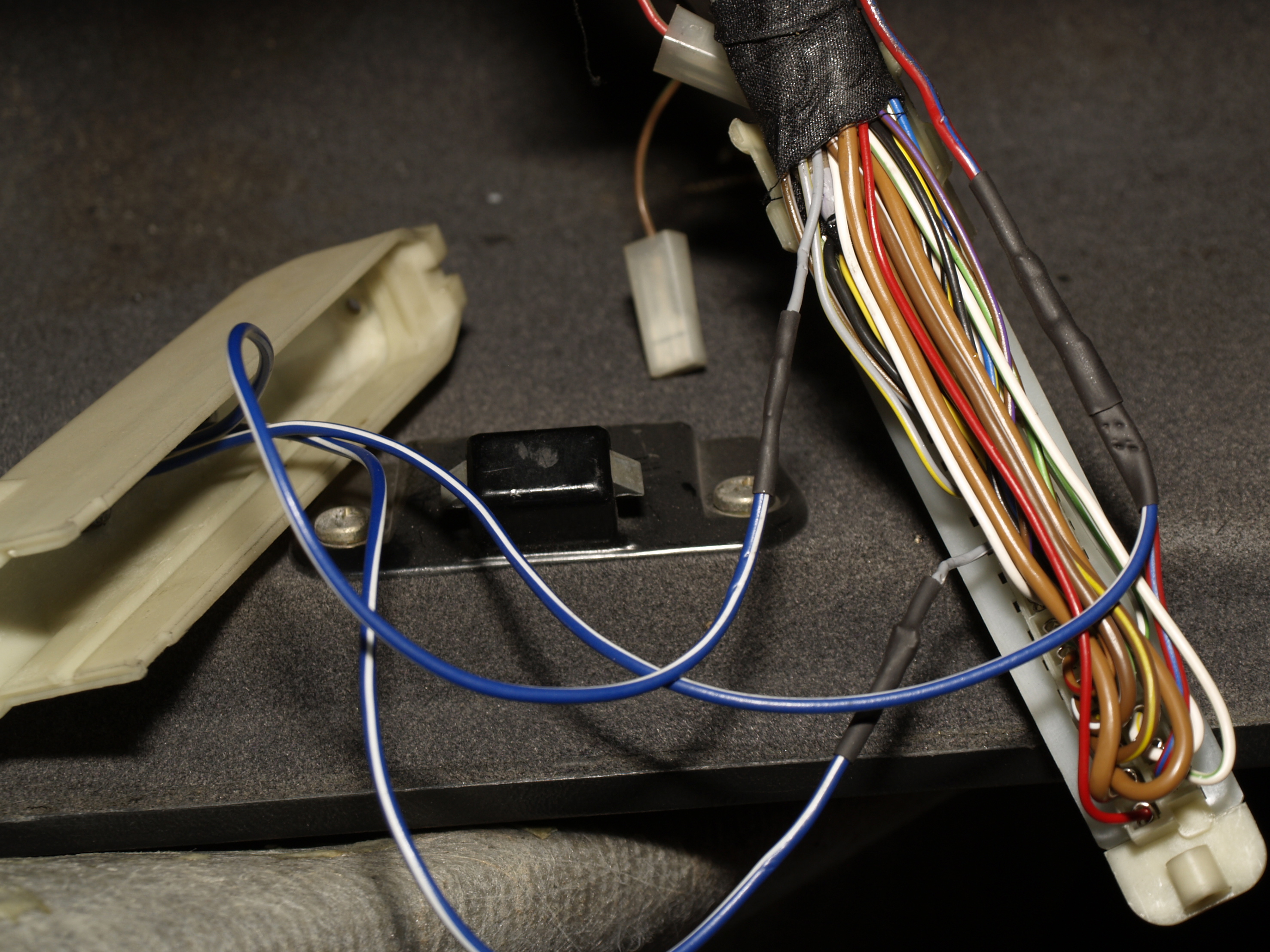
The second part of the winter work was more electricals, new alarm and replacing the Miller GENIII with their WAR programmable chip. I couldn’t decide what to tackle next but seeing as how the loom needed opening up to remove the old alarm stuff and put in the new, plus I had to connect the gauges with the senders, I started on the alarm first. I bought a Toad A101CL alarm on eBay last year from Southern Car Security and got it delivered to friends in England. I picked it up when we went over to visit. I chose the Toad as it was reasonably priced and seemed popular on various forums. Strangely enough I couldn’t find much in the way of reviews for stuff like this here in the Netherlands although I did find a couple of sites offering diy alarms reasonably priced. Miguel the owner of Southern Security was really helpful with the installation although he is really busy and a reply to the mail is sometimes the same day but sometimes a day or two later. I’ve not taken any pictures of the alarm installation as it would give the game away a bit if you see what I mean. Everything is neatly taped up in the loom or routed tidily under and in the dash. The installation itself went reasonably but finding the correct connections even with the BMW ETM (Electrical Troubleshooting Manual). If you don’t know of this Google it – you’ll need one for your exact model and year anyway. When I finished connecting it all up I got the necessary chirps from it but it kept giving me 3 when arming thereby informing me that either the doors, bonnet or boot were still open. I disconnected the bonnet and boot and found that the doors were working correctly but it took me a couple of evenings testing and tracing to work out what was wrong. Both bonnet and boot switches work, as with the doors, by grounding the switch connection, so that’s how I’d wired it up. However when closed (switch open) I was still getting a signal to ground. Eventually I found that the positive feed to the lamp itself was showing me a connection to ground except when the lights were on when it gave me 12v. I think BMW must use some sort of relay system which I haven’t bothered to delve into but I solved it by putting a 5A diode in both feeds. Problem 1 was now solved. Secondly the central door locking was not working and I eventually found the answer on a blogsite from another BMW owner. As I understood the ETM it was using positive switching but again due to the complexity of the BMW wiring system this was again wrong and after connecting the two alarm wires to earth, instead of the 12v feed, problem 2 was solved. Lastly I needed to adjust the ultrasonic sensor and so needed to get into the service mode, that took me a while to get right. Once in service mode you need to be pretty quick switching the ignition on and off to get it to work but eventually I got it to chirp and then proceeded to check everything including the ultrasonic sensor. That is now adjusted so that if the window is open it doesn’t go off until you stick your arm right in.
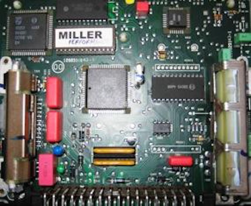
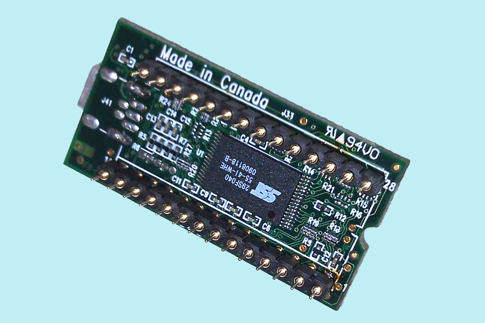
OK so the last part of the work was actually the easiest, installing the new WAR chip. Now the WAR chip is not actually a simple eprom like the oem chip or the GENIII, its a small printed circuit board with a set of pins through it to fit in the IC socket. It has a couple of larger chips and other components on it for the engine management, ram storage and the usb connection I presume.
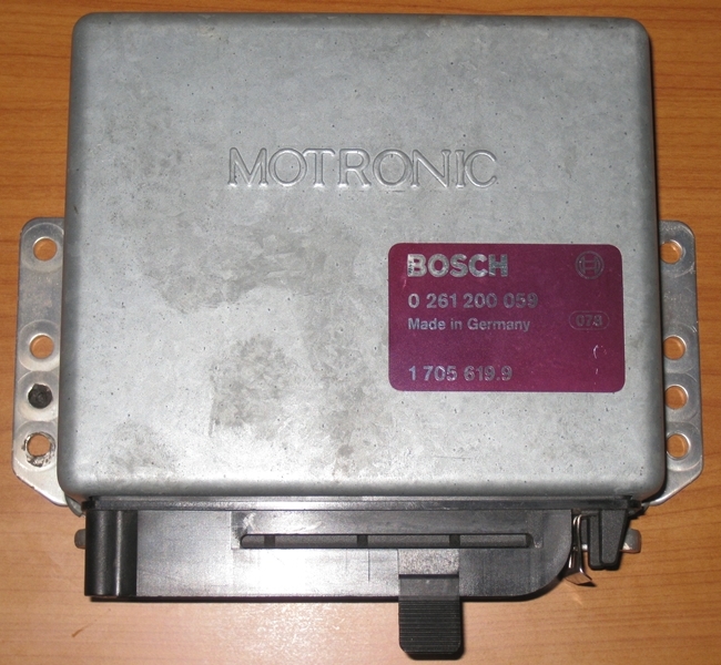
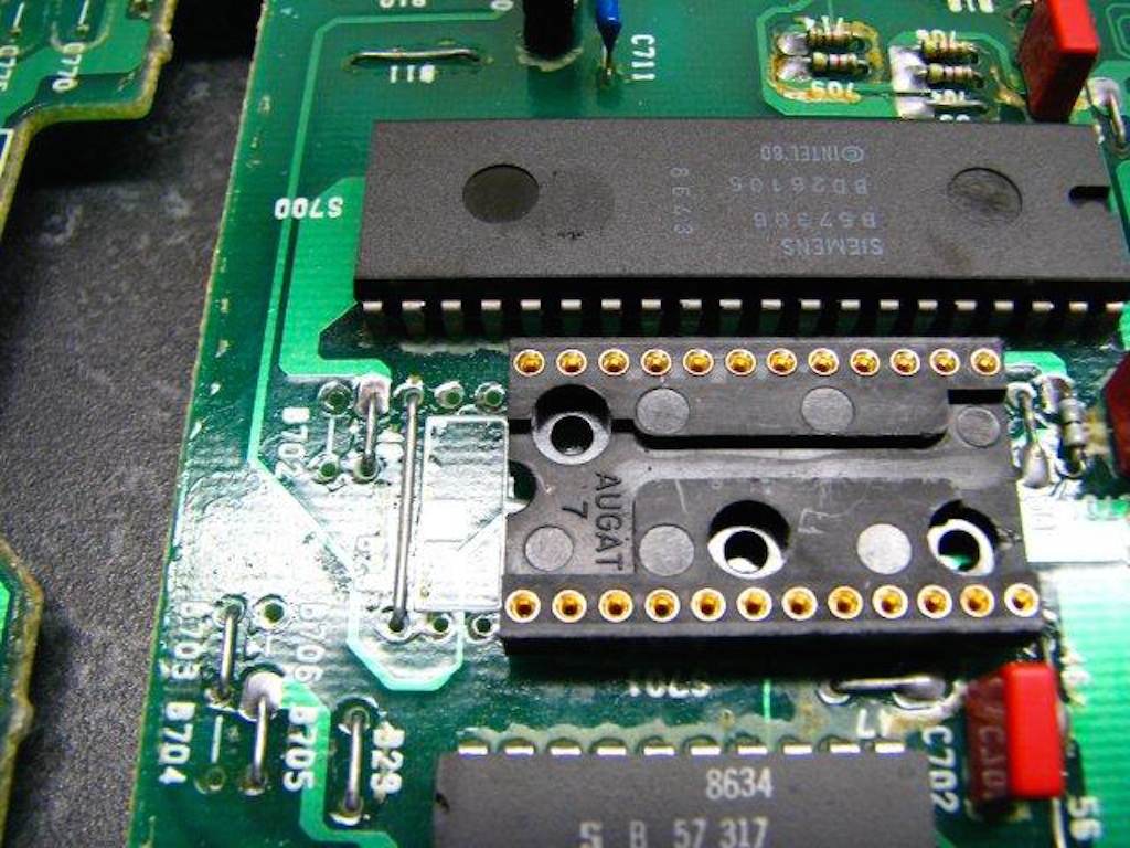
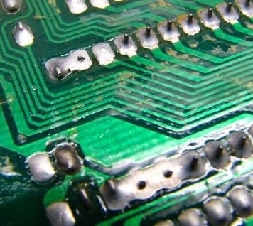
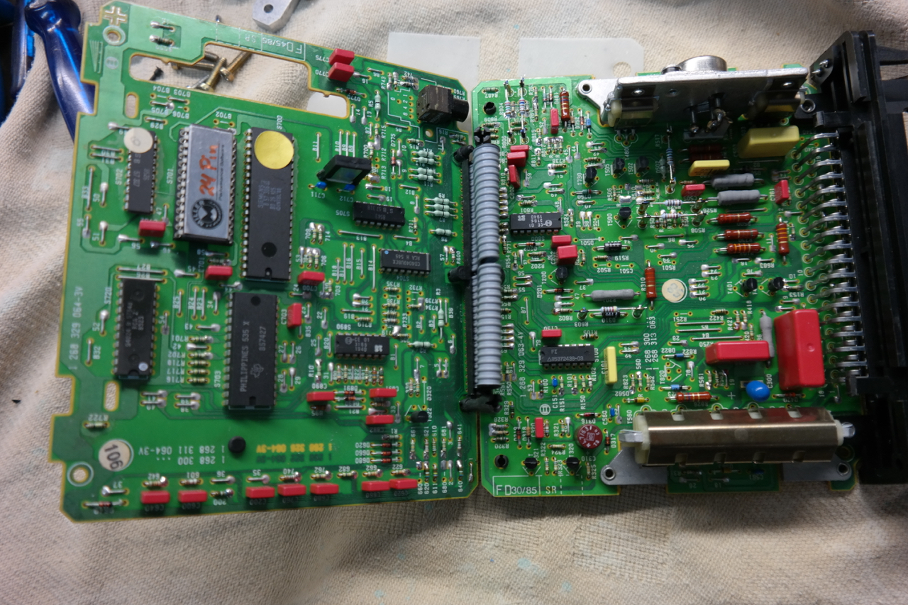
So the first job was to open up the DME casing and fold the hinged boards open to reveal the old GENIII chip top left, the silver one.
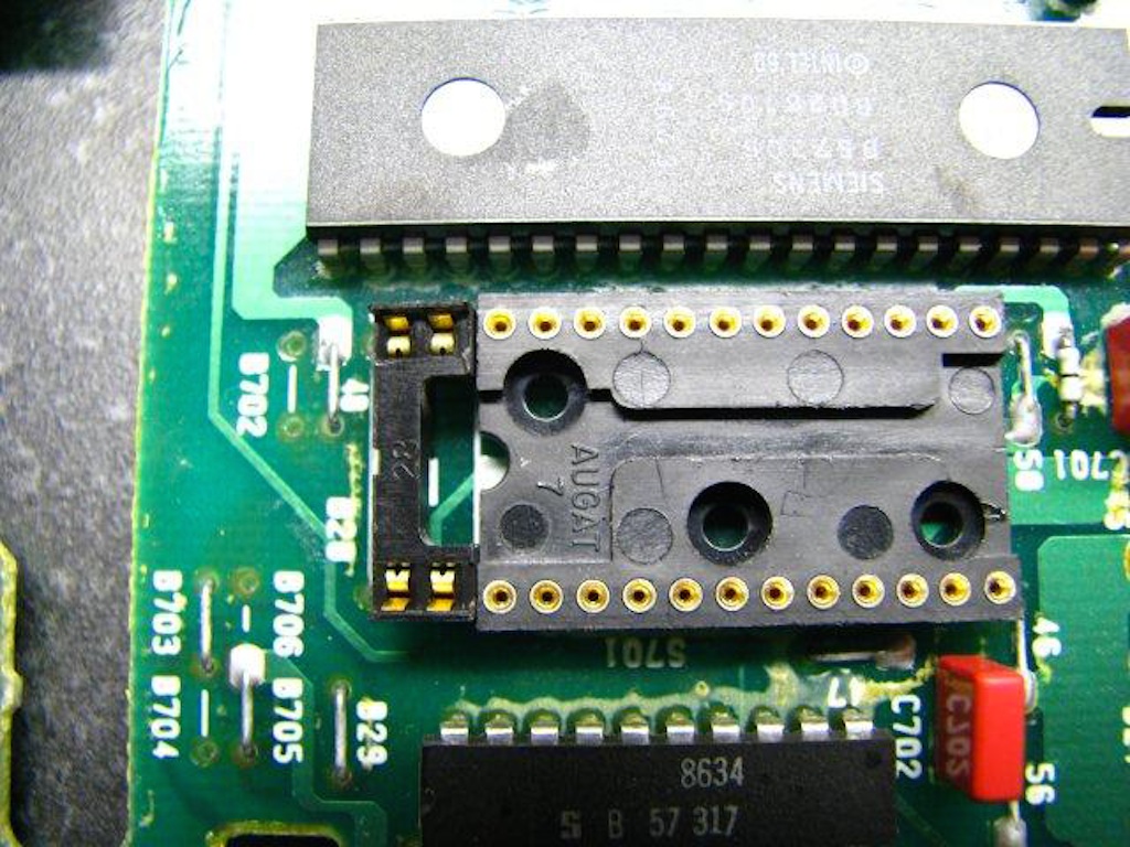
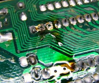
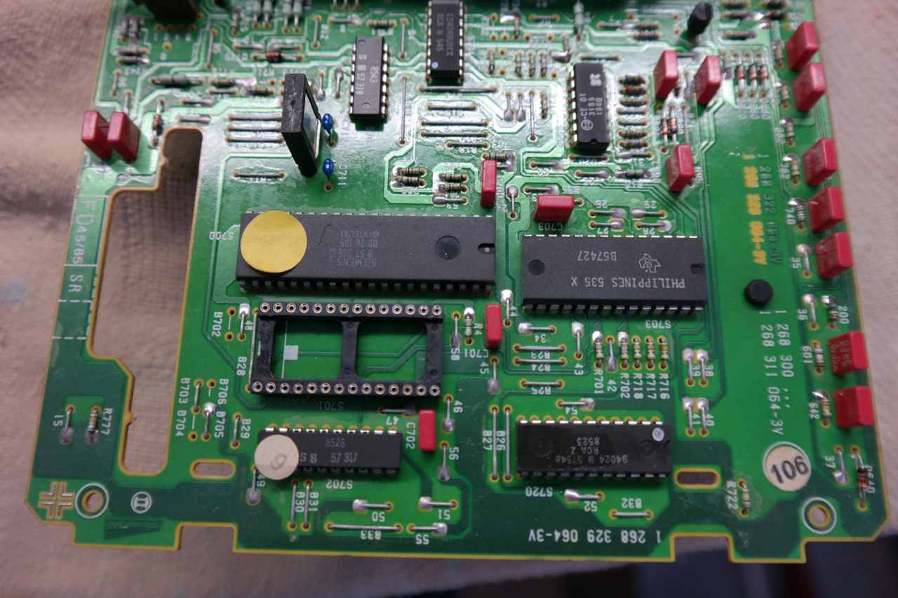
Once removed you can see the 28 pin eprom socket I installed when I did the original MAF conversion
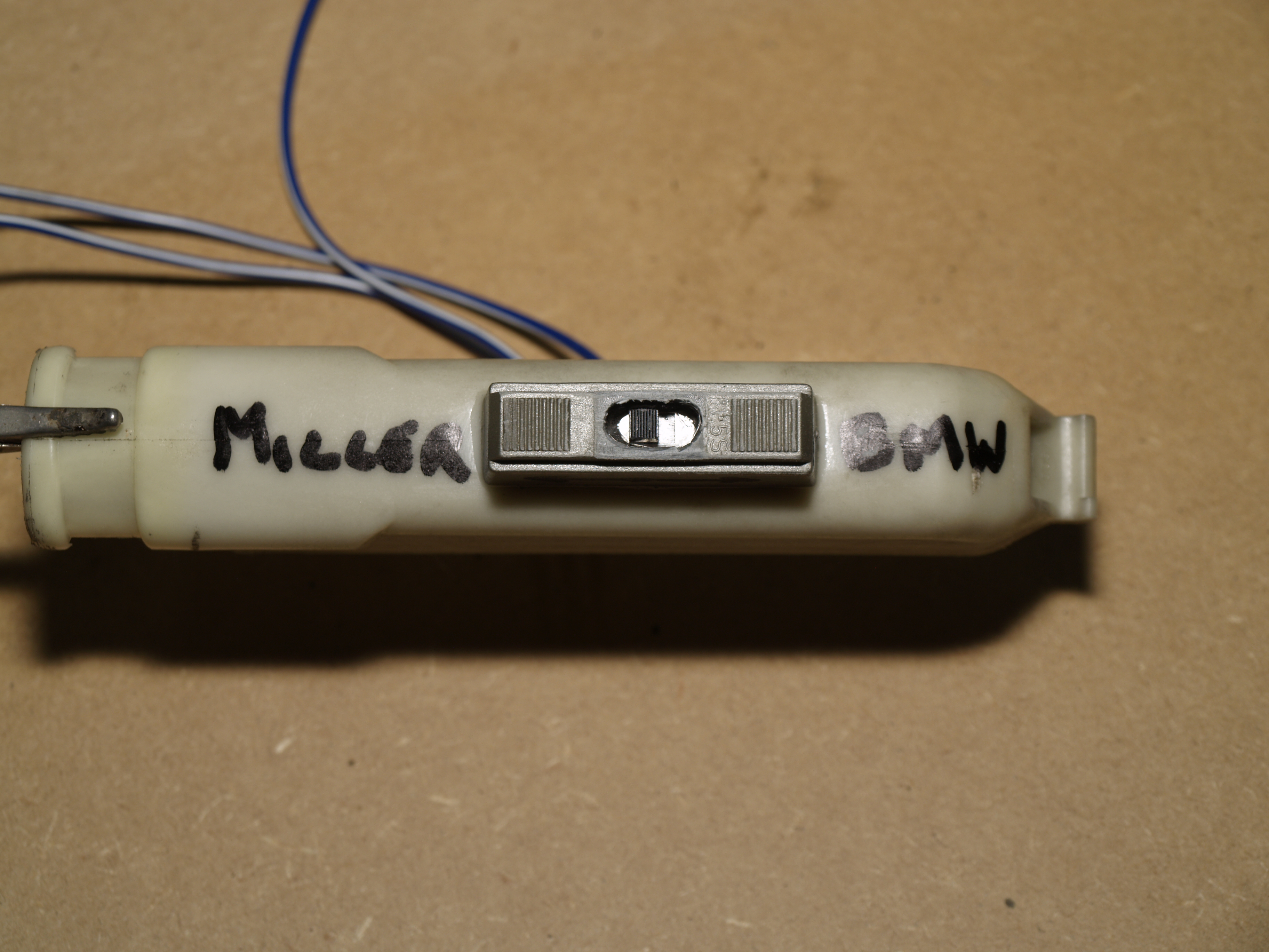
The WAR chip plugs in just like the old one. Here you can see the two supplied cables attached, the USB from the horizontal socket on the right and the cable for the tune selector switch from the vertical socket. Top left is a grommet round the cables to stop the casing chafing the cables.
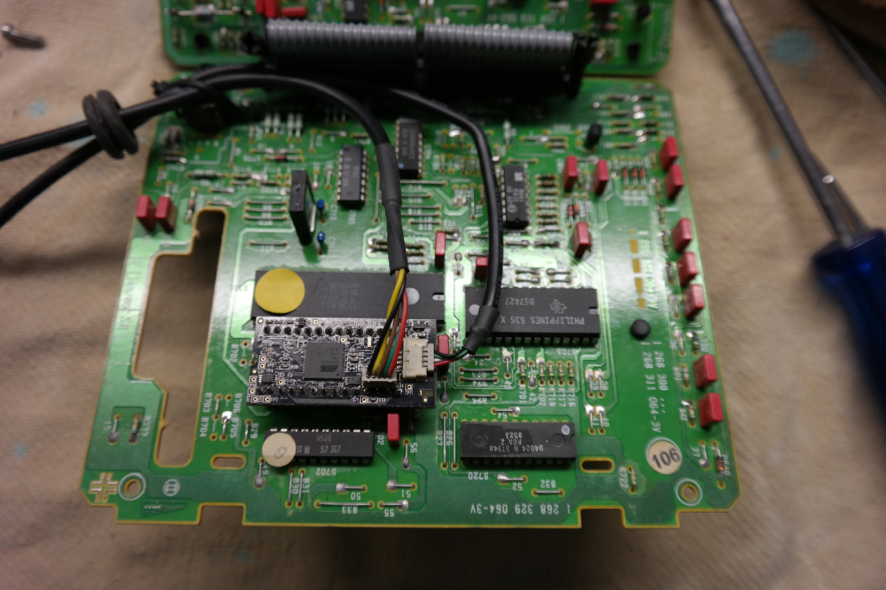
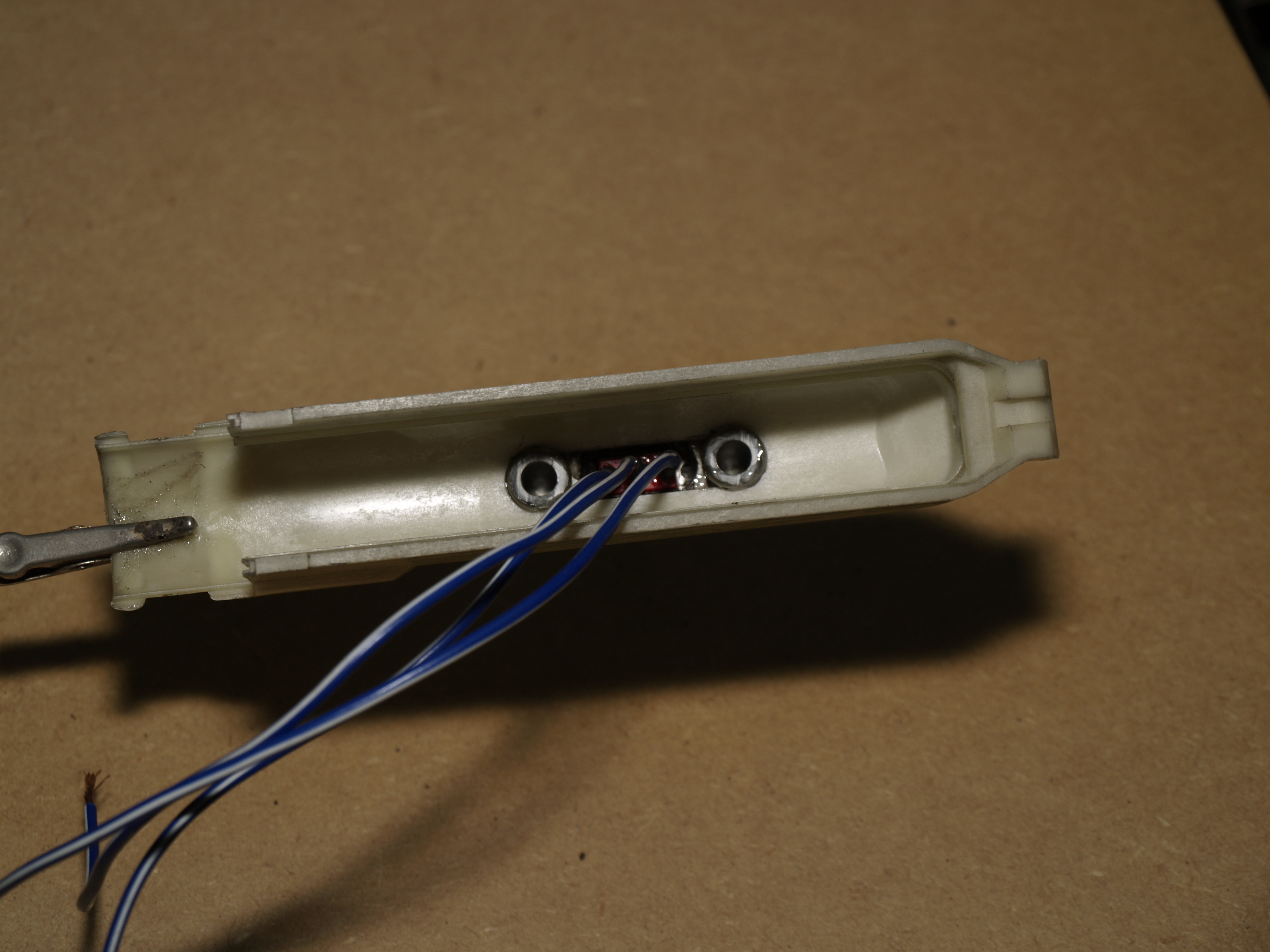
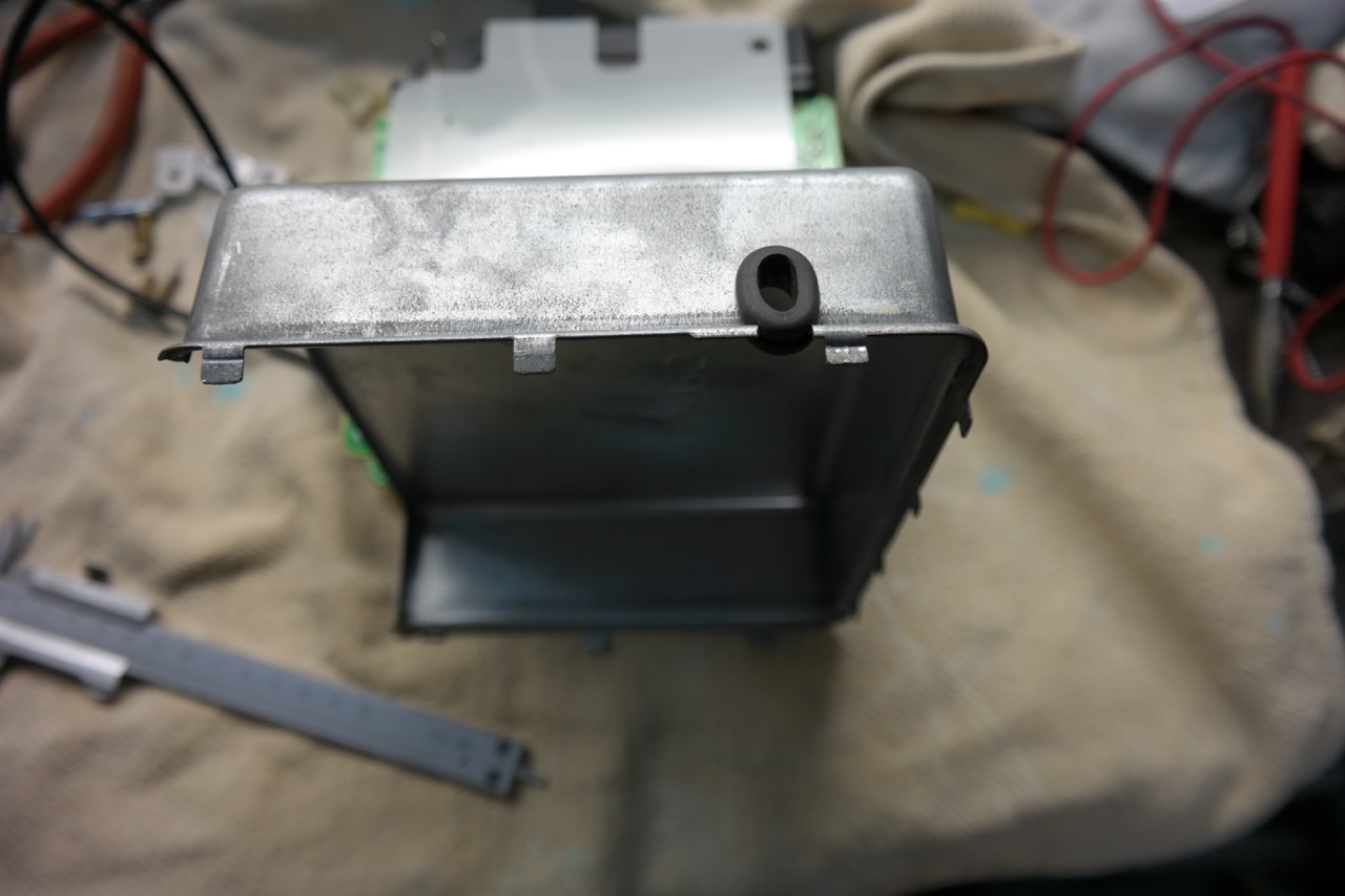
Here a shot of the casing with slot cut in it with the Dremel. Grommet takes on an oval shape in the slot to accommodate both cables snugly.
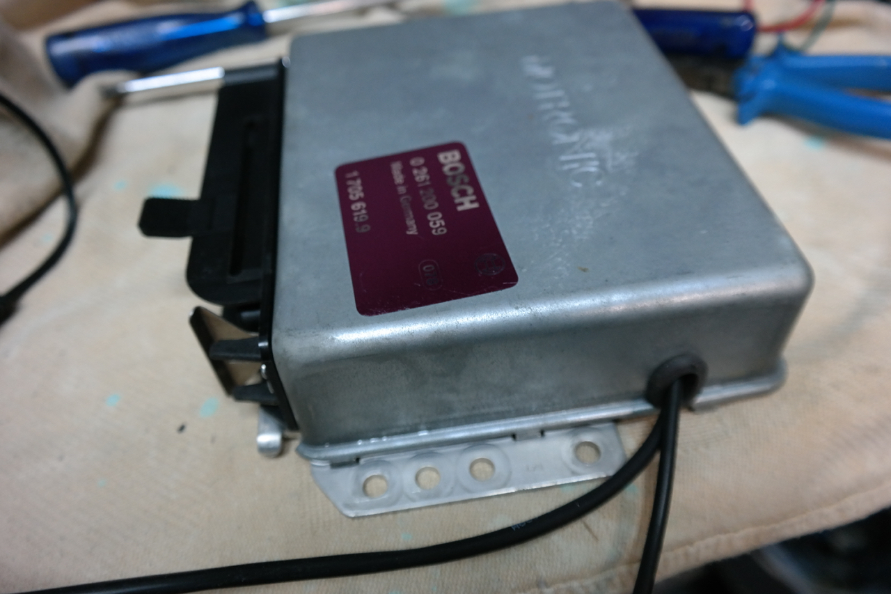
Once reassembled it looks like this ready to be refitted in the car.
The last job was installing Windows XP on an old laptop to use for the interface to the chip. The present WAR software won’t run on Windows 7 or later.