Problem number two that I encountered with the engine rebuild was the pilot bearing. For anyone who doesn’t happen to know, it’s the bearing in the rear end of the crankshaft which supports the nose of the transmission input shaft (notice that I didn’t use the English term gearbox as that has alternative connotations for US readers????) Ok, so there are various tricks on the net to remove this thing and the most popular is to pack the rear with grease and then insert a dowel and give it a good whack with a large hammer. Tried that – didn’t work – bearing was stuck solid. Alternative solution when it’s that stuck – use the factory tool.
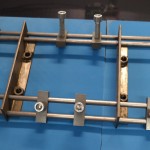
factory tool
Well, I didn’t have one and couldn’t get one quick over the weekend when I was working on it, apart from that they are not that cheap. So what do we do? We dig through the scrap box to see if we can construct something.
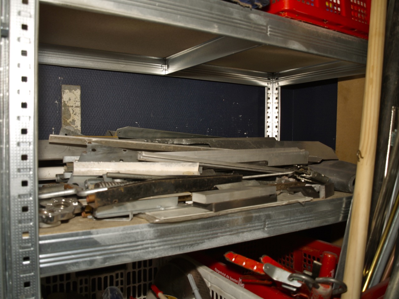
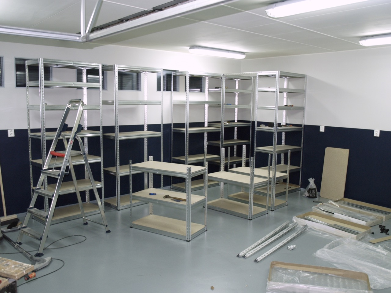
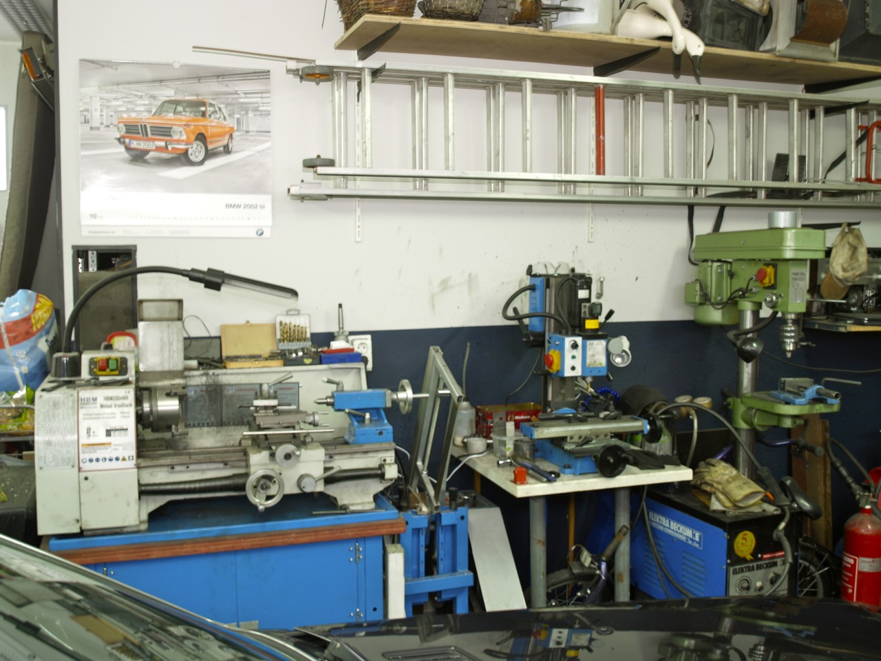
Scrap shelf
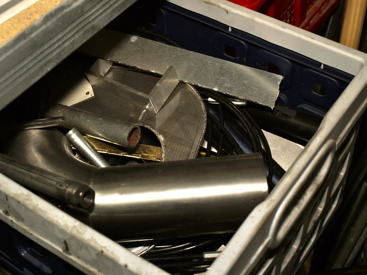
Scrap box
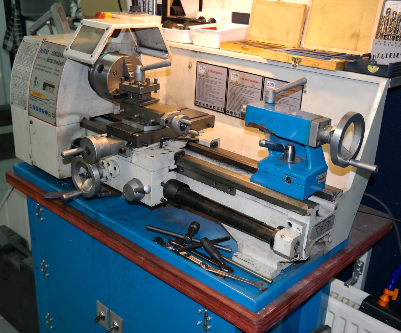
So I found a piece of steel tube which when turned slightly smaller on the lathe fitted snugly over the lip on the rear of the crankshaft that centres the flywheel.
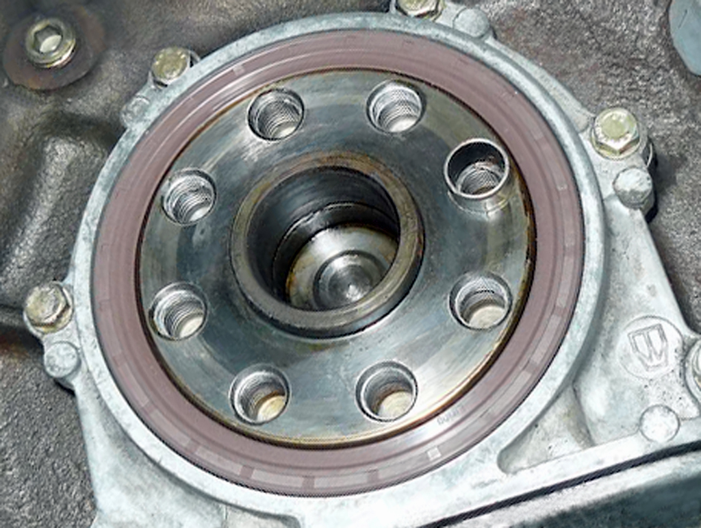
Crankshaft end
Here the old bearing has already been removed but a rusted example can be like the one below (found on the web) and then no amount of whacking a dowel with a hammer will shift it.
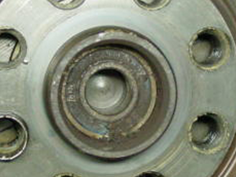
Rusted crankshaft end
So anyway after I’d prepared a 30mm length of the tube I found an 80mm length of 16mm threaded round bar, a 10mm length of 6mm threaded round bar and a couple of nuts to fit them.
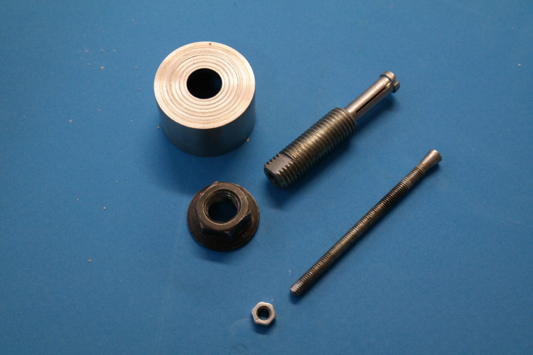
Separate components
Here you can see that I’ve actually turned these odd bits into something slightly more useful. The larger tube has been turned into a cup by brazing a piece of plate steel into one end, turned relatively smooth and a 16mm hole drilled in it.
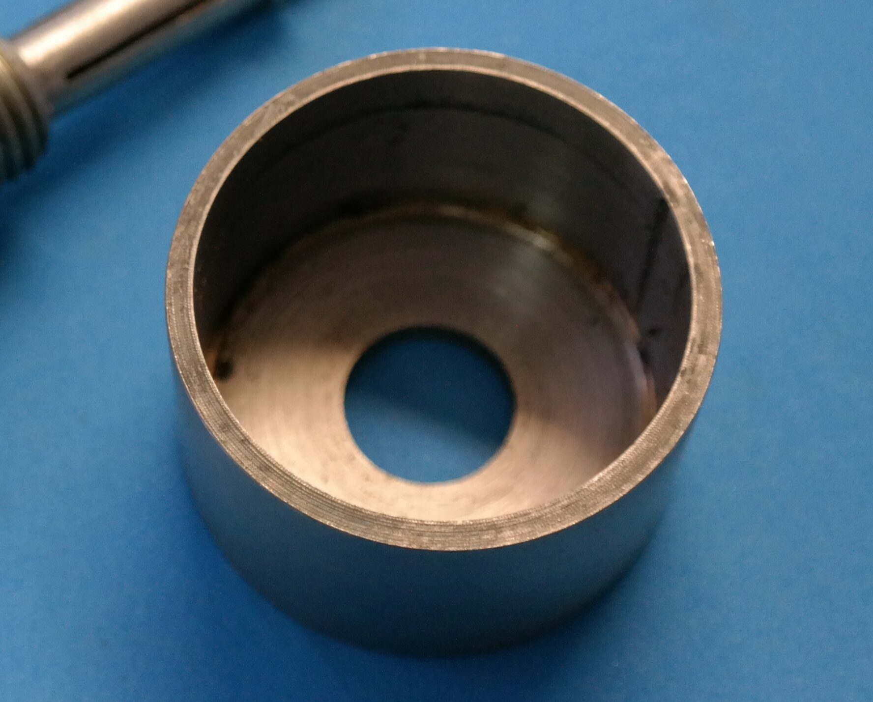
Basic positioning cup
The 16mm threaded round bar has been bored 6mm to accept the other threaded bar. One end has a couple of flats filed onto it and the other has been machined down to 10mm with a 12mm lip on the end. the turned end was then cross sawed through with a fine saw to form four quadrants. The smaller threaded bar had also flats filed on one end and on the other end a 10mm piece of 6mm i/d tube was brazed over it and then turned to form a taper. So then the smaller rod fits in the larger one like this.
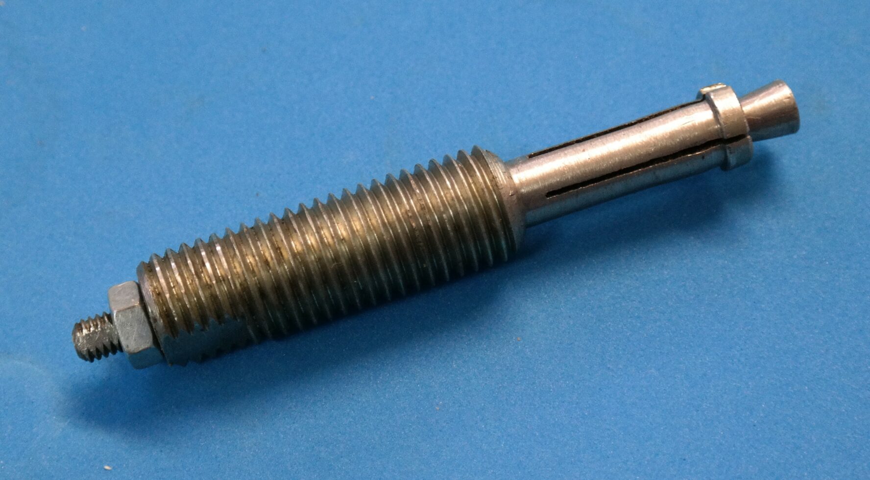
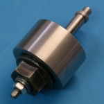
Extractor assembly
So to use it we first place this assembly above into the centre of the bearing and by holding the flatted end of the smaller shaft with a spanner or a mole grip, tighten the nut until the lip expands to fit inside the bearing and locks behind it. Then place the larger tube over the shaft and seat it round the lip on the crankshaft.
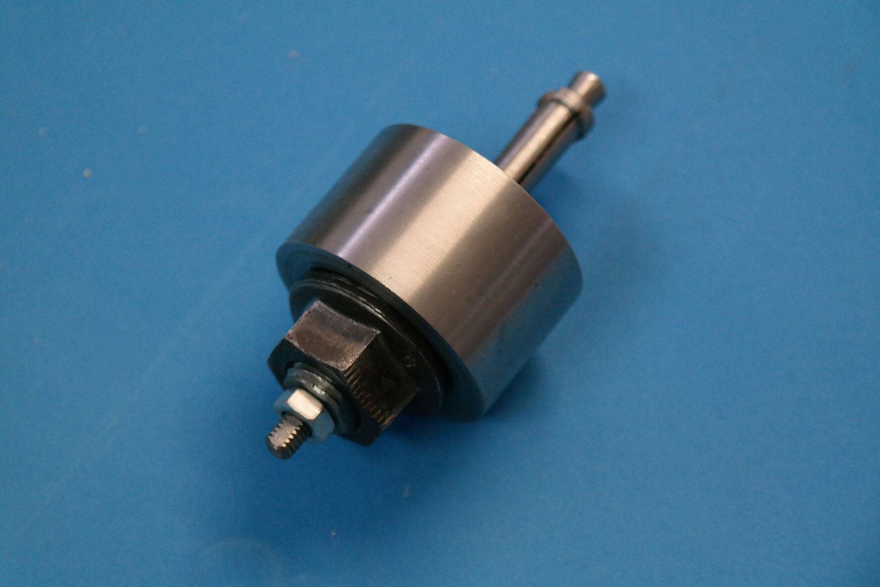
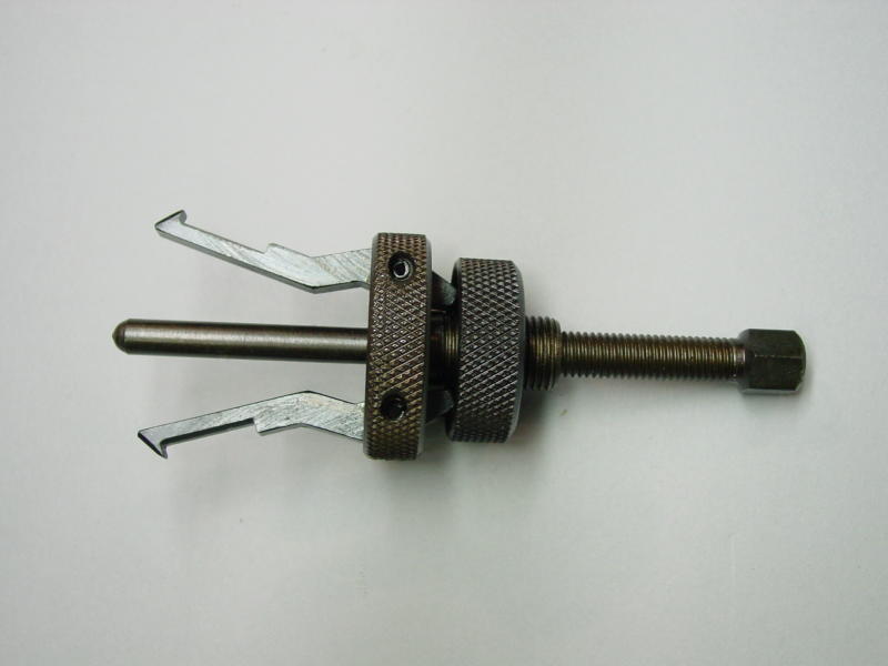
Complete assembly
You can then hold the flatted end with a spanner to stop it all turning and tighten the large nut which slowly extracts the bearing. Hey Presto!
Well I did actually spend a couple of hours fabricating the tool for what would have been 5 minutes usage and I can’t actually think when it will be used next, so was it worth it. Well yes… it got the job done and it gives an enormous amount of satisfaction to see that the idea worked and the tool (although a little Heath Robinson) is not a bad design. Anybody need to borrow it?